
What are the basic components of a pneumatic system?
Pneumatic systems cannot work without pneumatic components, because these pneumatic components constitute the pneumatic system just as human organs constitute the human body. This article will briefly introduce the basic components of a pneumatic system, as well as their functions and characteristics. Click on "What is the Pneumatic System?" for a brief introduction to pneumatic systems. Click on "What are the differences between Hydraulic System and Pneumatic System?" to learn about the differences between pneumatic and hydraulic systems.
You can quickly navigate to the chapters you are interested in through the Directory below, and the Quick Navigator on the right side of the browser.
CONTENTS
§1. What are pneumatic components? |
§2. Air source unit |
§3. Actuator unit |
§4. Control unit |
§5. Auxiliary unit |
§1. What are pneumatic components?
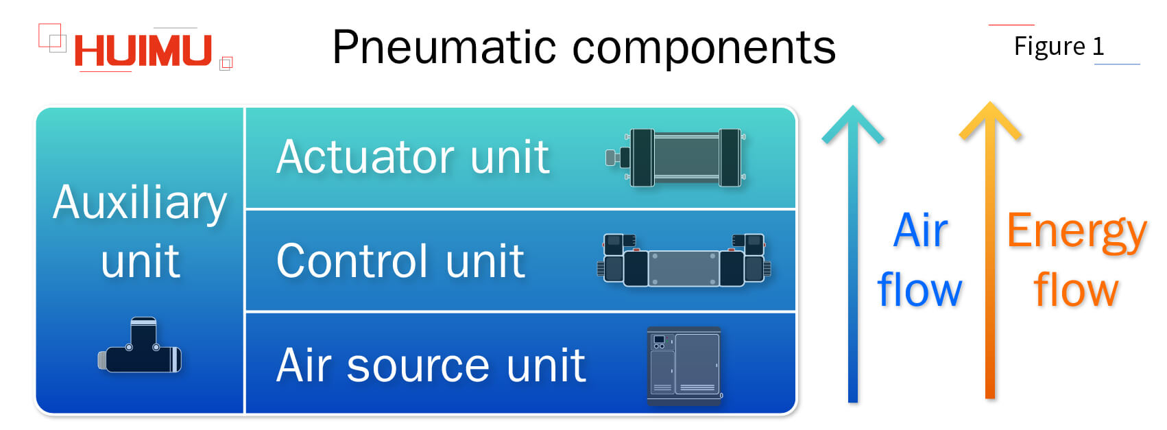
The pneumatic system is a kind of industrial automation system composed of pneumatic components, with gas (mainly compressed air) as the power source and working medium. According to the main functions, pneumatic components can be divided into the air source unit, the actuator unit, the controller unit, the auxiliary unit, etc. By interconnecting simple pneumatic components through piping, a complex pneumatic circuit can be formed and power can be output to the load through pneumatic actuators. The air source unit converts the mechanical energy supplied by the air compressor into the pressure energy of compressed air and stores the compressed air in a storage tank for use in other units. To improve the service life of the pneumatic components, water, oil and solid particles need to be filtered out of the compressed air, so the air source unit also includes air source treatment equipment. The actuator unit is capable of converting the pressure energy of compressed air into the mechanical energy of moving parts. Pneumatic actuators (e.g., pneumatic cylinders, air motors, air grippers) can apply mechanical force to a load by means of linear or rotary motion. The controller unit is able to control the operation of pneumatic actuators by controlling their flow and pressure. The flow and pressure required for each pneumatic actuator are different and need to be controlled individually. Failure to control them precisely can reduce the efficiency of the pneumatic actuator and result in unnecessary energy waste. The auxiliary unit (e.g. mufflers, sensors, pipes and fittings) are not very impressive, but are essential in pneumatic systems.
§2. Air source unit
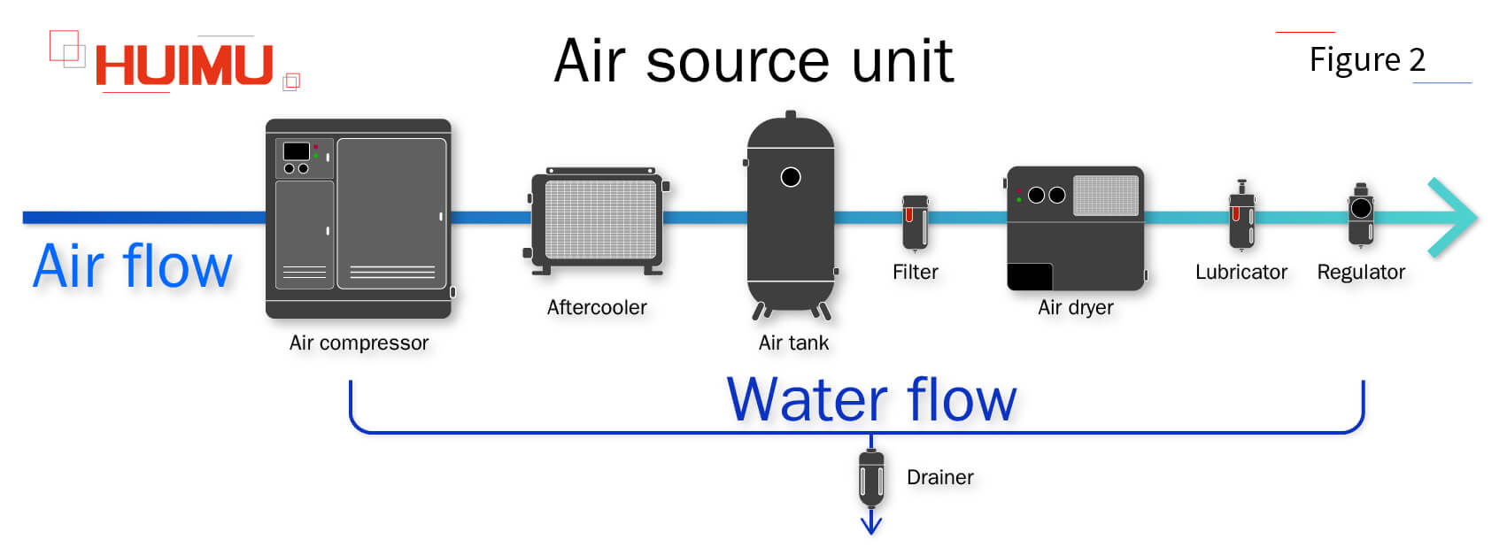
-The air source unit is capable of supplying clean and stable compressed air to the pneumatic system.
2.1 Air compressor
The compressed air is an important medium for transferring energy in a pneumatic system, which cannot be obtained directly from the atmosphere, but only from the high pressure compression of an air compressor. The air compressor draws air from the atmosphere and gradually reduces its volume to raise its pressure. According to the compression methods, air compressors can be divided into piston air compressors, rotary vane air compressors, and rotary screw air compressor. Since air releases a lot of heat during the compression process, the compressor room must be designed with a ventilation system to eliminate the waste heat generated by the compressor. At the same time, since the compressed air in an air compressor can reach a temperature of 180°C, the compressed air contains a large amount of gaseous impurities (such as gaseous water and vaporized compressor oil). If not filtered, these gaseous impurities will condense in the piping after leaving the compressor, which will corrode the pneumatic components, cause blockage of valves as well as moving parts and affect the normal operation of the pneumatic system. An aftercooler can usually be installed at the outlet of the air compressor to filter out these gaseous impurities. The aftercooler will rapidly cool the hot compressed air to below 40°C to condense the gaseous impurities, and drain them through a drain valve. The cooling method of aftercoolers can be divided into water-cooling or air-cooling. Water-cooled aftercoolers provide good cooling effect and are therefore the most common cooling method, while air-cooled aftercoolers can be used where water is difficult to obtain. It should be noted that although the aftercooler removes most of the gaseous impurities, a small amount will still enter the piping, which can be captured by maintaining the inclined angle of the piping. If the compressed air needs to be further purified, then air source treatment components is required.
2.2 Air tank
Air storage tank, also known as pressure vessel, is equipment specifically designed to store compressed air. According to the pressure, air tanks can be divided into high-pressure air tanks and low-pressure air tanks. According to the structure, air tanks can be divided into dry air tank and wet air tank. Air tanks are generally metal materials, such as carbon steel, stainless steel, and other alloy materials, there are also high-strength carbon fiber material. Air tank have good sealing, which can effectively improve the energy density of the pneumatic system and output constant pressure compressed air. Since air expands and contracts thermally, in order to avoid losing the energy of compressed air in the form of heat, air tanks need to have excellent thermal insulation in addition to good sealing. The energy in the air tank is not affected by the external environment, even in the case of power failure, the energy in the storage tank can still support the continuous and stable operation of the pneumatic system until the air pressure of the compressed gas in the air tank falls below the rated value, which helps to reduce the working frequency of the air compressor, improve its service life and reduce the waste of energy. The residual gaseous water in the compressed air is further cooled to condensate in the air tank, which can be discharged from the bottom of the air tank.
2.3 Air source treatment
2.3.1 Filter
During the operation of an air compressor, the oil on its piston forms an oil mist that mixes with the compressed air. If the temperature of the air compressor is too high, this oil mist will be carbonized by the high temperature. In addition, as the compressed air also contains rust, dust and other solid impurities, these solid impurities will combine with the oil mist to form sludge. This sludge can enter pneumatic components such as solenoid valves, cylinders and pressure gauges with compressed air and block their air inlets and outlets, causing wear and movement disorders. Although these impurities can be filtered out by installing an aftercooler at the outlet of the air compressor, the filtering capacity of the aftercooler is usually very limited (only impurities above 5μm can be filtered out) in order to avoid reducing the efficiency of the air compressor due to excessive pressure differences. Therefore, it is usually necessary to install filters to further filter out minor impurities in order to improve the quality of compressed air and ensure the stable operation of the pneumatic system.
2.3.2 Air dryer
When air is compressed, the amount of water vapor contained in a unit volume of compressed air increases significantly. If this water vapor is not completely filtered out by the filter, then this water vapor will cool in the piping and combine with dust to form slurry, causing clogging and excessive wear on the pneumatic components. So a dryer is required to further remove the water from the compressed air. In addition, since air is elastic and its volume is greatly affected by temperature, a dryer can be used together with a cooler to stabilize the temperature of the compressed air to improve its stability.
2.3.3 Regulator
The regulator, also known as pressure reducing valve, can reduce the air pressure of the air source to the rated pressure of the pneumatic components. At the same time, the pressure reducing valve can keep the air source in a constant state to reduce the damage to the valve and pneumatic actuator caused by the sudden change of air pressure of the air source.
2.3.4 Lubricator
Since pneumatic systems are closed circuits, it is not possible to add lubricant directly to the surfaces of moving parts. However, compressed air is used as the working medium for pneumatic systems, so atomized lubricant can be injected into the compressed air through lubricator, allowing moving parts to be lubricated with the flow of compressed air. But, with the popularity of oil-free lubrication technology, the use value of lubricator is gradually weakening.
2.3.5 Air source treatment unit
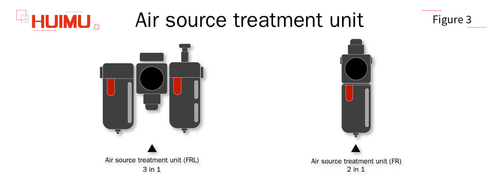
The air source treatment unit (FRL) is a combination of Filter (F), Regulator (R) and Lubricator (L). Since these three air source treatment components are necessary for the air source treatment process, they are usually integrated into a single air source treatment unit to reduce the installation space occupied. However, as more and more pneumatic products are oil-free lubricated, the lubricator are used less and less frequently, and the air source treatment unit (FRL) becomes air source treatment unit (FR) when there is no lubricator.
2.3.6 Drainer
The drainer, also known as drain valve, is used to remove condensate from pneumatic systems. Drainers are usually installed at the bottom of air compressors, air tanks, air dryers, and precision filters. Drainers can be divided into manual drainers and automatic drainers. The manual drainer is drained through a manual valve, which is time-consuming and labor-intensive and also causes loss of compressed air. The automatic drain is mainly controlled by the float inside the drain; when the buoyancy of the float is less than the pressure exerted by the spring, then the automatic drainer is closed; when the buoyancy of the float is greater than the pressure exerted by the spring, then the automatic drainer is open. The automatic drainer only drains water without venting, so it can achieve zero air loss. If a pre-filter is installed in front of the automatic drainer, it can effectively filter impurities such as oil sludge and rust from entering and causing blockage of the drainer. If the automatic drainer is equipped with a large flow hole, the drainer can easily clean the rust, sludge and other impurities in the compressed air, which can effectively prevent the occurrence of clogging. High-frequency automatic drainers are usually equipped with mufflers to reduce the ambient noise generated. Electronic drainers can be adjusted by a timer to adjust the drain interval and drain duration.
§3. Actuator unit
-The air source unit is capable of supplying clean and stable compressed air to the pneumatic system.
3.1 Pneumatic cylinder
3.1.1 Direct-acting cylinder
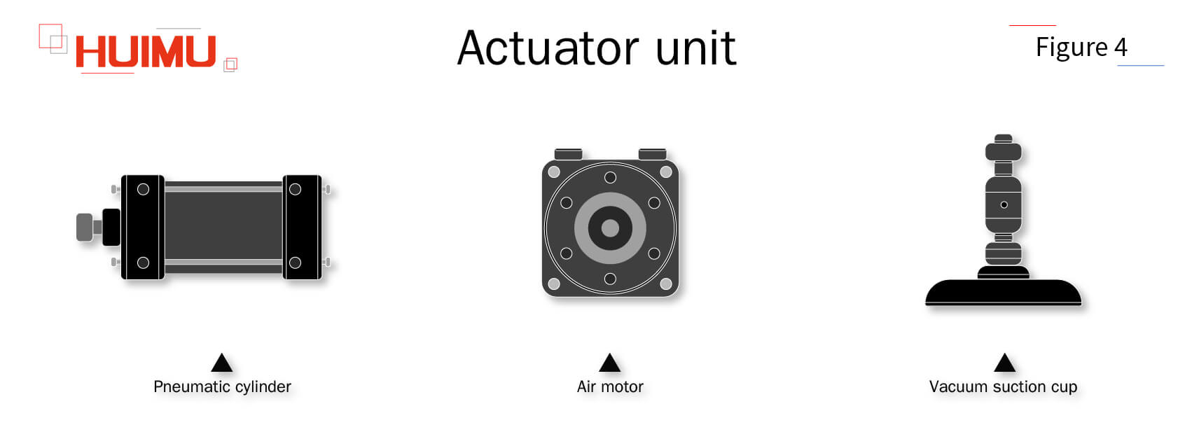
The direct-acting cylinder is a kind of pneumatic actuator that does linear reciprocating motion, mainly composed of cylinder barrel, end cap, piston, piston rod and seal, etc. The compressed air converts the pressure energy into mechanical energy by driving the piston in a reciprocating motion inside the oval cylinder barrel. The cylinder needs oil mist in compressed air to lubricate its piston, while the lubrication-free cylinder does not. In order to prevent the cylinder piston from hitting the cylinder head, the cylinder is generally equipped with a cushion device, but usually its cushioning capacity is weak, so for safety reasons, whether the cylinder itself has a cushion device, the cylinder needs to be equipped with a hydraulic buffer outside, and the cylinder stroke needs to leave a margin of 10 ~20mm. The output capacity of the cylinder is related to the bore, if the bore is too small, its output force is not enough, but if the bore is too large, the cylinder will become bulky, its cost will increase, and its air consumption will increase. The movement speed of the cylinder depends on the input flow of the compressed air, the size of the cylinder inlet and exhaust port and the size of the inner diameter of the tube. There are many types of cylinders, such as standard cylinder, composite cylinder, free Installation cylinder, compact cylinder, pen cylinder, dual-rod cylinder, slide cylinder, rod-less cylinder, impact cylinder, diaphragm cylinder, etc.
3.1.2 Oscillating cylinder
The oscillating cylinder is a kind of pneumatic actuator that does reciprocating oscillation, mainly composed of rear cylinder head, inlet plunger, cylinder body, piston, front cylinder head, vane, piston rod, etc. The inner chamber of the oscillating cylinder is divided into two chambers by the vane, and the alternating air supply of the two chambers allows the output shaft to make reciprocating rotary motion within a certain angle (oscillation angle less than 280°). Because of the small cross-sectional area of the chambers, the air consumption of the oscillating cylinder is small and does not affect the pressure of the air source. The oscillating cylinder is mainly used for valve opening and closing, robot arm movement, and etc.
3.2 Air gripper
The oscillating cylinder is a kind of pneumatic actuator that does reciprocating oscillation, mainly composed of rear cylinder head, inlet plunger, cylinder body, piston, front cylinder head, vane, piston rod, etc. The inner chamber of the oscillating cylinder is divided into two chambers by the vane, and the alternating air supply of the two chambers allows the output shaft to make reciprocating rotary motion within a certain angle (oscillation angle less than 280°). Because of the small cross-sectional area of the chambers, the air consumption of the oscillating cylinder is small and does not affect the pressure of the air source. The oscillating cylinder is mainly used for valve opening and closing, robot arm movement, and etc.
3.3 Air motor
The air motor, also known as pneumatic motor, is a prime mover that uses compressed air as the working medium, which normally can be used as the rotary power source of more complex devices or machines. Air motors use the expansion effect of compressed gas to convert pressure energy into mechanical energy. Compared with electric motors, air motors have the advantages of small size, high adaptability, easy commutation, step-less speed regulation, high starting torque, can be started with load, simple structure, long service life, no spark, no heat, no explosion, no pollution, etc. According to the structure, air motors can be divided into vane air motor, piston air motor, compact vane air motor, compact piston air motor.
3.4 Vacuum suction cup
The vacuum suction cup, also known as vacuum spreader, is a vacuum equipment used for work-piece carrying, mainly composed of suction cup and suction cup ring, and driven by vacuum pressure generated by vacuum generating device (such as vacuum generator, vacuum pump). When the object needs to be carried, the vacuum generator makes the negative air pressure inside the vacuum suction cup, which can firmly suck the object under the action of atmospheric pressure; when the object reaches the destination, the vacuum generator stops working, which makes the negative air pressure inside the vacuum suction cup disappear, and the object is free from the vacuum suction cup. The greater the negative air pressure inside the vacuum suction cup, the closer the vacuum suction cup is to the object and the greater the suction force, but the suction cup is in direct contact with the object, so it is very easy to wear. As one of the cheapest, most convenient and non-invasive means of carrying work-pieces, vacuum suction cups are widely used in electronic device assembly, automobile assembly, automatic handling machinery, light industry machinery, food machinery, medical machinery, printing machinery, plastic products machinery, packaging machinery, forging machinery, robotics and other automation fields.
§4. Control unit
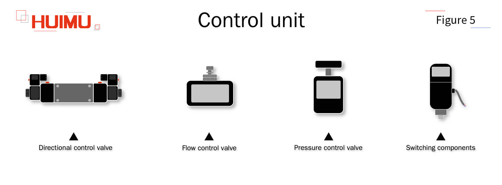
-The control unit is used to control and regulate the pressure, flow and direction of compressed air so that the pneumatic actuator can work according to the required function and performance.
4.1 Directional control valve
The directional control valve is used to control the flow path of compressed air within a pneumatic system.
4.1.1 Reversing valve
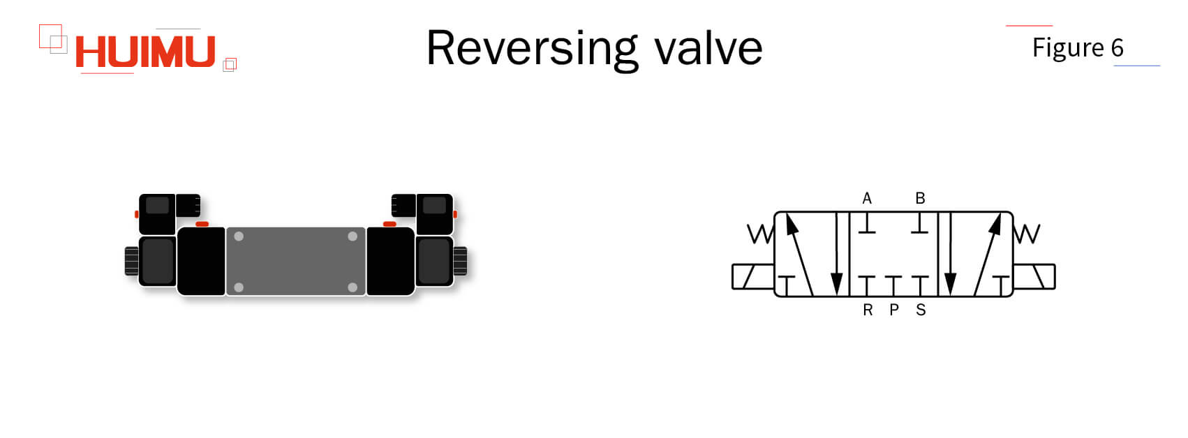
The reversing vale, also known as directional vale, is mainly composed of valve body and spool. Through the relative movement of the spool and the valve body, the reversing valve can control the turn on, cut off and flow direction of compressed air. According to the driving method of spool movement, directional valves can be divided into electromagnetic directional valves, pneumatic-controlled directional valves, manual-controlled directional valves, machine-controlled directional valves, etc. The position of the spool in the body of the reversing vale can be changed, and each position represents one working state of the reversing vale. The total number of air ports (input port, output port and exhaust port) on the valve body represents the ways of the reversing vale. Under different working state, different ways will be formed between these air ports to turn on or cut off the air flow, or change its flow direction. Take five-way three-position (5/3) solenoid valve as an example, three boxes represent three different working states, five dots of each box represent five air ports. The symbol "┻" or "┳" in the box indicates that the pathway is cut off, and the arrow in the box indicates that the pathway is turned on (the direction of the arrow only represents the relative direction, not the actual direction). The direction of compressed air flow can be adjusted by moving these boxes.
4.1.2 Check valve
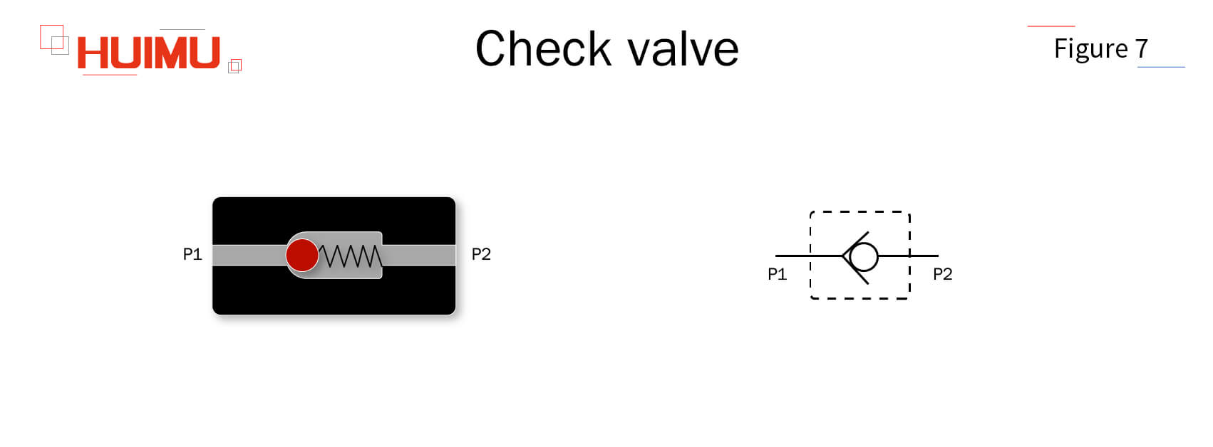
The check valve, also known as one-way valve, is used in pneumatic systems to prevent the reverse flow of compressed air, which works similar to the diode in the electronic system. When the compressed air flows forwardly and its pressure reaches the minimum opening pressure of the check valve, the compressed air is allowed to pass through. When the compressed air flows reversely, the compressed air is blocked and cannot flow freely. Check valves are used to protect pneumatic components that do not allow back-flow, such as air compressors, pressure pumps, coolers, etc.
4.1.3 Shuttle valve
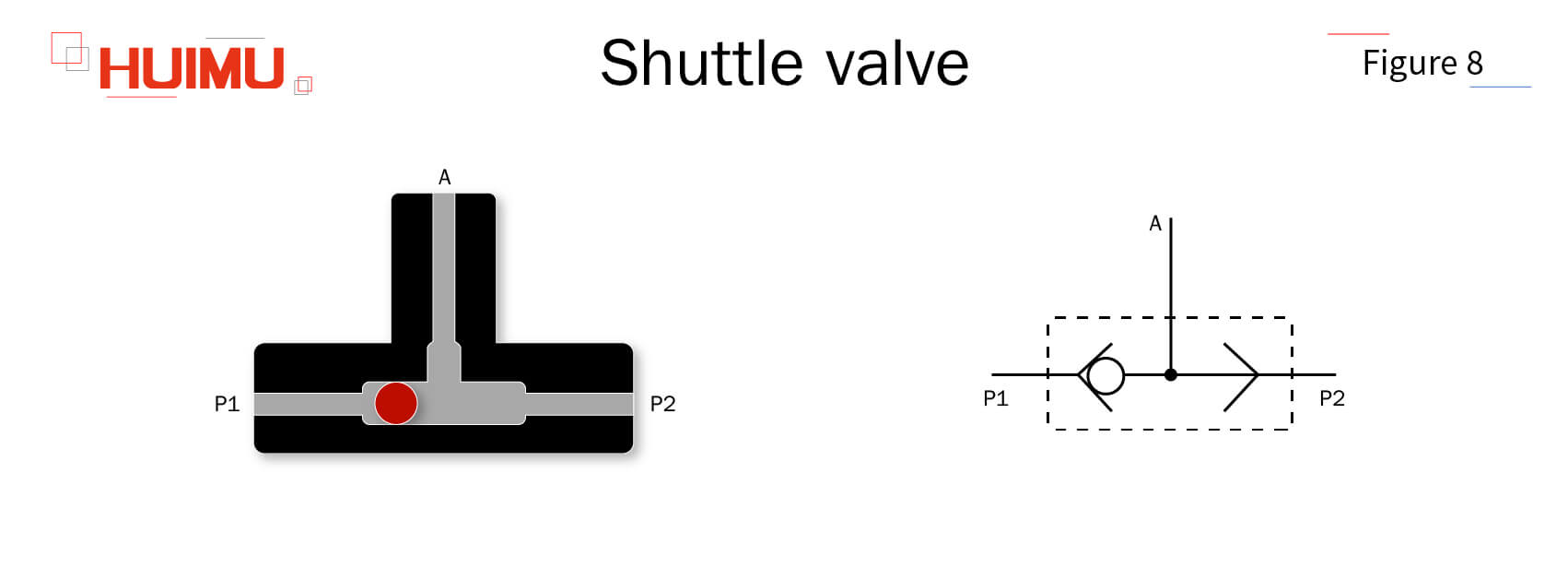
The shuttle valve, also known as two way control valve or two way check valve, is equivalent to a combination of two check valves, which works similar to an "or gate" in a logic circuit. The shuttle valve has two inlets P1 and P2 and one outlet A. P1 and P2 can be connected to A, but P1 and P2 cannot be connected to each other. If there is a signal input to either inlet, a signal will output from the outlet. If both P1 and P2 have signal input, the one with higher pressure will be output through A, and the other will be blocked by the internal check block, which acts as a pressure selector, so no matter which inlet has higher pressure, the outlet will always have the same pressure as the higher one. If there is no signal input from both P1 and P2, there will be no signal output from A. Due to the characteristics of the internal structure of the shuttle valve, it works with little resistance interference, so the air pressure loss is small and it can switch quickly to input the control signal to the pneumatic actuator in sequence.
4.2 Flow control valve
The directional control valve is used to control the flow path of compressed air within a pneumatic system.
4.2.1 Throttle check valve
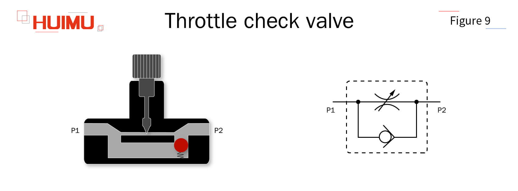
The throttle check valve, also known as one-way throttle valve. is the simplest flow control valve which consisting of a throttle valve and a check valve connected in parallel. The throttle valve in the throttle check valve is used to regulate the air flow in the forward direction, and the check valve in the throttle check valve allows the reverse air flow to return smoothly, so the throttle check valve can regulate the movement speed of the pneumatic actuator in the forward direction and allow the pneumatic actuator to return quickly in the reverse direction. However, since the throttle valve does not have negative feedback, it cannot compensate for the speed instability caused by load changes, so the throttle check valve is generally used only for pneumatic actuators with little load changes or low requirements for speed stability.
4.2.2 Flow proportional valve
The flow proportional valve is a new type of electronic pneumatic valve for flow regulation, which can reduce the number of pneumatic components, simplify the pneumatic system, and reduce the cost of manual operation.. The proportional solenoid in the flow proportional valve is capable of continuously, proportionally and remotely regulating the output flow according to the electrical signal. The flow proportional valve has two control modes, switch mode and continuous mode. In the switch mode, the flow proportional valve is similar to a solenoid reversing valve, with only two states of maximum flow (100%) and minimum flow (0%). In continuous mode, the flow proportional valve can adjust the output flow rate according to the input flow rate at a continuously adjustable set ratio (0~100%).
4.2.3 Speed control valve
The speed control valve is used to regulate the movement speed of the cylinder, which composed of the fixed difference pressure reducing valve and the throttle valve in series. The throttle valve is installed in the inlet and outlet of the cylinder. The inlet throttle valve of the cylinder is used to directly adjust the flow of the supply pipe, while the outlet throttle valve of the cylinder is used to adjust the flow of the exhaust pipe. Since the exhaust flow control is more stable, the movement speed of the cylinder is usually controlled by adjusting the outlet throttle. The fixed differential pressure reducing valve is used for automatic compensation of load changes, so that the pressure difference between both sides of the throttle valve is a fixed value, to eliminate the impact of load changes on the flow.
4.2.4 Cushion valve
The cushion valve, also known as buffer valve, is used to prevent the piston of the cylinder from hitting the cylinder head when it reaches the end of its stroke due to excessive movement speed. The cushion valve is usually installed near the air port of the cylinder, and its bore is much smaller than the air port of the cylinder. When the piston of the cylinder is fast moving to the end, the cushion sleeve on the piston will form a sealed cushion chamber with the cushion seal, and the air inside the cushion chamber will be adiabatically compressed to form an air cushion with reverse force on the piston, thus slowing down the piston until it stops. The cushioning capacity of the cushion valve can be adjusted by adjusting the opening of the cushion valve. However, it should be noted that if the opening is too large, the cushioning capacity of the cushion valve will become very weak; if the opening is too small, the piston will not be able to return quickly due to the long cushion stroke.
4.2.5 Quick exhaust valve
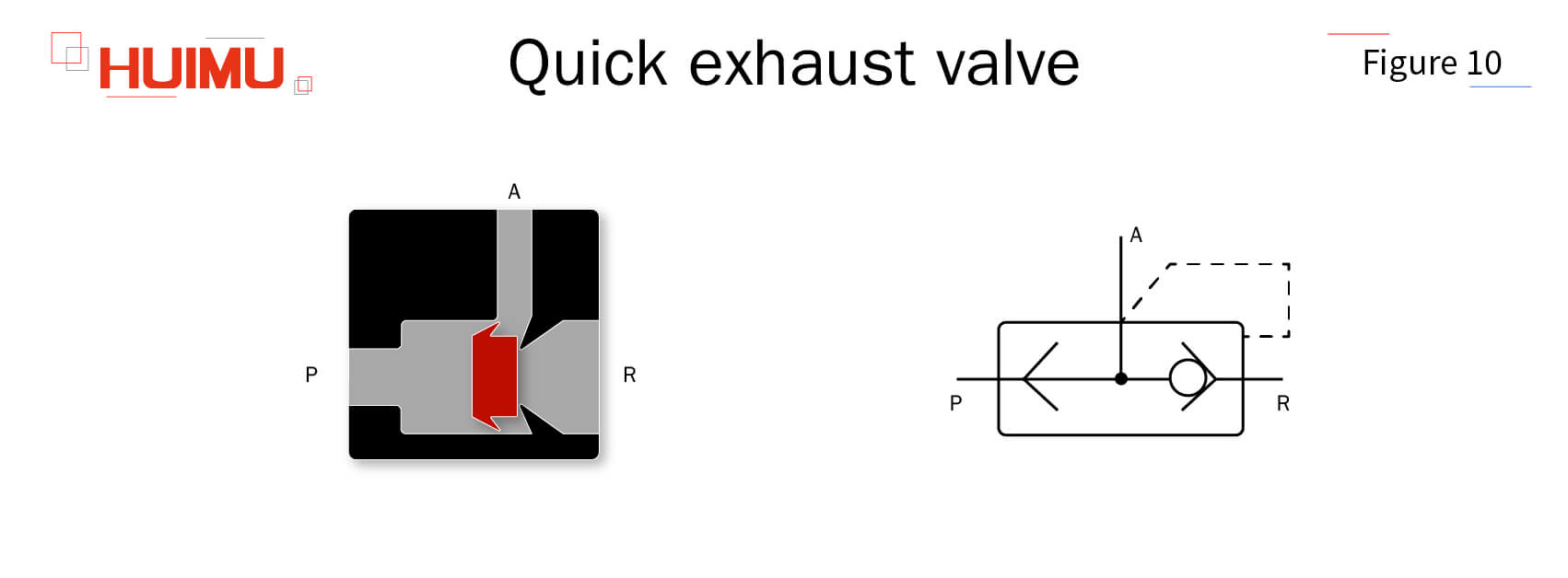
The quick exhaust valve is usually installed between the reversing valve and the pneumatic actuator for quick exhaust. The quick exhaust valve has three air ports, which are connected to the reversing valve (P), the pneumatic actuator (A), and the atmosphere (R). If the pneumatic actuator needs to be opened quickly, the air from the outlet of the pneumatic actuator will enter A, push the spool to block P, and then quickly exhaust to the atmosphere through the large bore exhaust port R without going through the reversing valve. If the pneumatic actuator needs to be closed, the air will enter P from the reversing valve, push the spool to block R, and then enter the pneumatic actuator through A to close the pneumatic actuator slowly. A muffler is usually required because the quick exhaust valve generates noise during the quick exhaust process.
4.3 Pressure control valve
The pressure control valve is able to adjust the pressure to the desired pressure of the pneumatic element and keep the pressure stable at the desired pressure value.
4.3.1 Relief valve
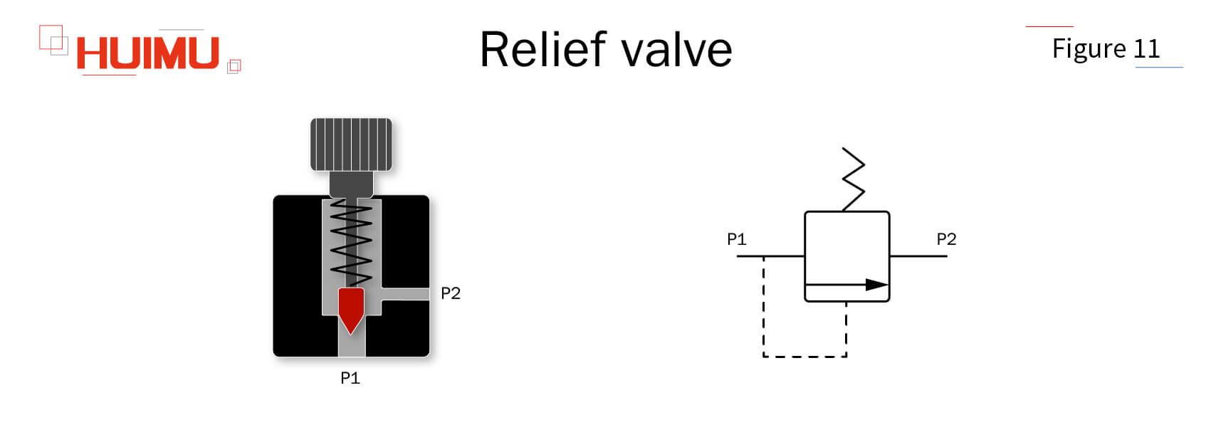
The relief valve, also called safety valve, is used to protect pneumatic components from damage due to excessive pressure. The set pressure of the relief valve is set by a spring, and the balance between air pressure and spring force determines the working state of the relief valve. When the air pressure at the inlet is less than the set pressure of the relief valve, the air pressure is less than the spring force, and the outlet of the relief valve is in the closed state. When the air pressure at the inlet exceeds the set pressure of the relief valve, the air pressure is greater than the spring force, and the outlet of the relief valve is in the open state, and will discharge part of the air to the atmosphere to keep the pressure of the pneumatic system within a safe range, that is, the relief valve determines the maximum pressure of the pneumatic system.
4.3.2 Pressure reducing valve
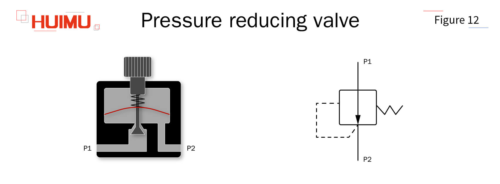
The pressure reducing valve, also known as pressure regulating valve, is used to reduce the air pressure of compressed air to the required low pressure. The pressure reducing valve is mainly composed of a flexible diaphragm, a needle valve, a spring, and an adjustment handle. The adjusting handle is used to set the pressure value of the pressure reducing valve. By changing the local resistance can consume the energy of compressed air and reduce the air pressure. When the air pressure is lower than the set value, the needle valve opens, and the pressure reducing valve is in the open state. When the air pressure is higher than the set value, the needle valve is closed, and the pressure reducing valve is in the closed state.
4.3.3 Booster valve
The booster valve, also called air booster pump, is used to raise the air pressure of compressed air to the required high pressure. The booster valve is mainly composed of booster chamber, drive chamber, check valve, pressure regulating valve, reversing valve, etc. The pressure regulating valve is used to set the air pressure value of the booster gas. When the air enters the booster valve, it is divided into two branches, one of which enters the booster chamber through the check valve, and the other enters the drive chamber through the pressure regulating valve and reversing valve. The air in the drive chamber will push the piston to reciprocate rapidly, making the air in the booster chamber continuously pressurized. When the air pressure of the booster chamber reaches the set value of the pressure regulating valve, the pressurized air will be discharged from the booster valve.
4.3.4 Pressure stabilizing valve
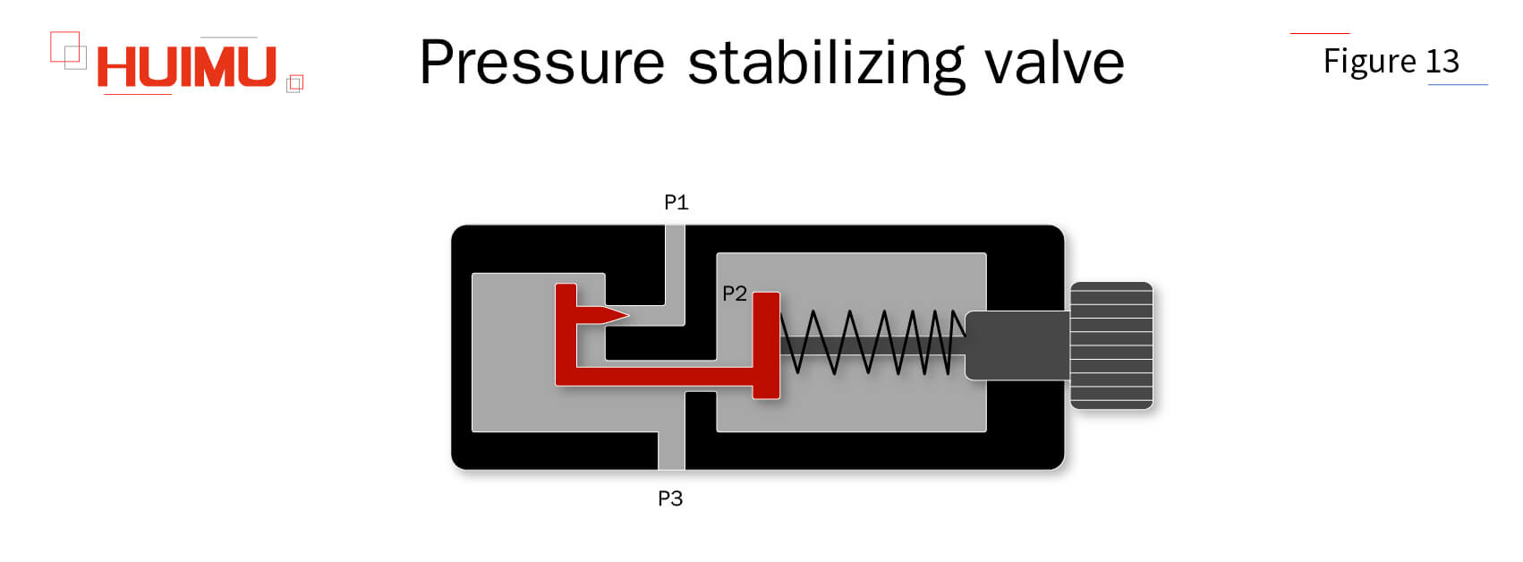
The pressure stabilizing valve is used to provide constant reference air pressure. The pressure stabilizing valve is mainly composed of bellows, needle valve, spring, and adjusting handle. The adjusting handle is used to set the pressure value of the pressure stabilizing valve. When the pressure at the inlet P1 increases, resulting in an increase in the pressure at P2, the air pressure pushes the bellows to the right, driving the needle valve to reduce the opening of the inlet, which eventually makes the pressure at the outlet P3 at a stable value. When the pressure of inlet P1 decreases, the pressure of P2 decreases, and the spring force pushes the bellows to the left, driving the needle valve to increase the opening of the inlet, finally making the pressure of the outlet in a stable value.
4.3.5 Sequence valve
The sequence valve is used to manipulate the sequence of operation of the actuators in multiple branches. The operating state of the sequence valve is controlled by the pressure at the control port. When the pressure at the control port reaches the set value, the sequence valve opens and allows the actuators to operate. By controlling the operating status of multiple sequence valves, it is possible to make multiple actuators work in sequence. Although the sequence valve is very similar to the relief valve in structure and working principle, and can replace the relief valve in some cases, the relief valve is working passively and the sequence valve is working actively, so the sequence valve cannot be used to limit the pressure of the pneumatic system.
4.3.6 Pressure proportional valve
The pressure proportional valve is a new type of electronic pneumatic valve for pressure regulation, mainly composed of pressure sensor, flow proportional valve, control circuit, etc.. The pressure proportional valve is equipped with flow proportional valves at both the outlet and inlet ports. By controlling the opening of these two flow proportional valves, the pressure proportional valve is able to regulate the air pressure at the outlet port. The control circuit is used to set the opening of these two flow proportional valves, and the pressure sensor is used to feed the air pressure at the outlet to the control circuit.
4.3.7 Vacuum generator
The vacuum generator is a vacuum component that uses a positive pressure air source (compressed air) to generate negative pressure. The operating principles of vacuum generators can be divided into Venturi principle, Bernoulli principle and Coanda principle. Vacuum generators are widely used in industrial automation, such as machinery, electronics, packaging, printing, plastics and robotics, for adsorption and handling of various materials (e.g. glass, silicon wafers, etc.).
4.4 Switching components
Switching components are used to detect the operating status of pneumatic components and convert them into control signals.
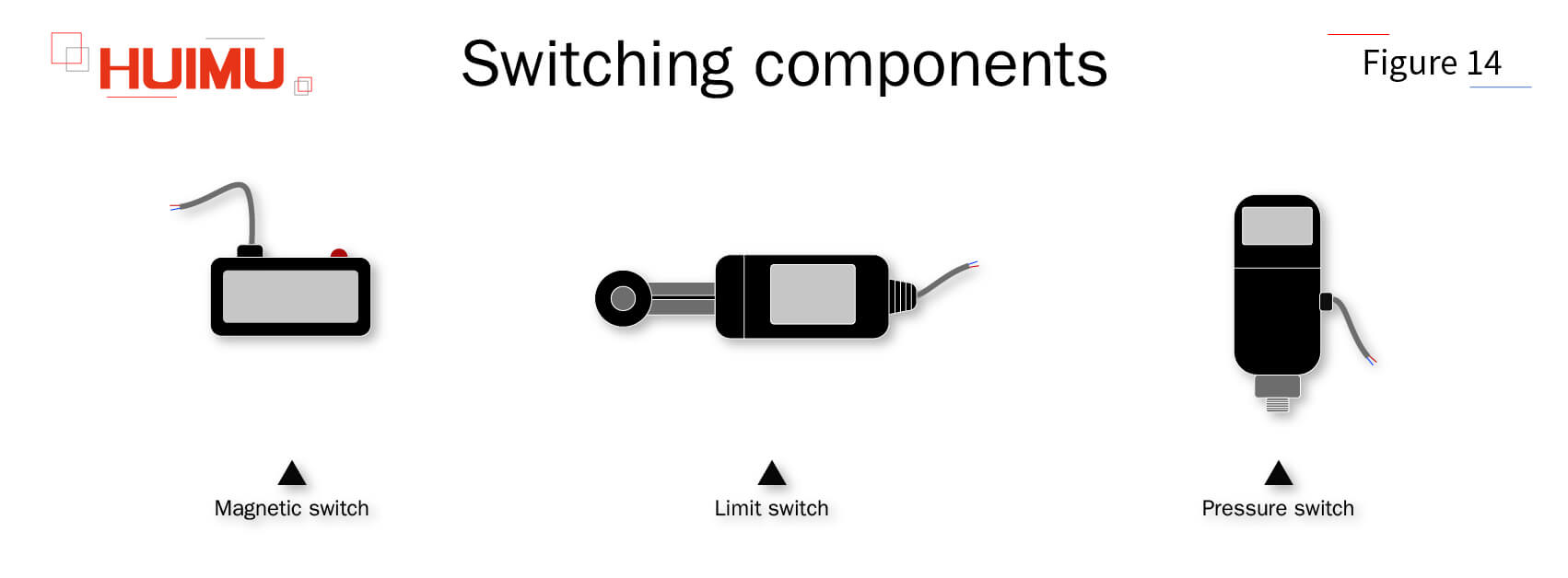
4.4.1 Magnetic switch
The magnetic switch is used to detect the position of the piston in the cylinder and convert it into a control signal. The magnetic switch consists of a permanent magnetic ring, a reed switch, a protection circuit, an action indicator, etc. The permanent magnet ring is mounted on the piston. The reed switch is mounted on the cylinder housing and is used to control the operating state of the solenoid reversing valve. When the piston is close to the reed switch, it will magnetize the reed plate, which will trigger it to conduct and make the solenoid reversing valve start working. When the piston moves away from the reed switch, the magnetizing effect is reduced and the reed switch is disconnected, making the solenoid reversing valve to stop working. By controlling the operating state of the solenoid reversing valve, the magnetic switch is able to control the reciprocating motion of the cylinder piston.
4.4.2 Limit switch
The limit switch, also known as travel switch, is used to detect the position of a moving part and convert it into a control signal. The limit switch is usually mounted on a moving part, and the contact block is mounted in a fixed part. As the moving part moves, when the mechanical contact on the limit switch touches the contact block, an electrical signal is generated. This electrical signal will be transmitted to the control circuit and performs the corresponding operation, such as turning on or off the cylinder, turning on or off the air motor, changing the operating status of the solenoid valve, etc.
4.4.3 Pressure switch
Pressure switches are used to detect the pressure in a pneumatic system and convert it into a control signal. When the pressure in the pneumatic system is higher or lower than the rated safety pressure, the elastic element in the pressure switch will produce displacement, opening the internal switching element and sending an alarm and control signal to the control circuit. When the pressure in the pneumatic system returns to the rated safety pressure, the elastic element in the pressure switch automatically resets, shutting off the internal switching element.
§5. Auxiliary unit
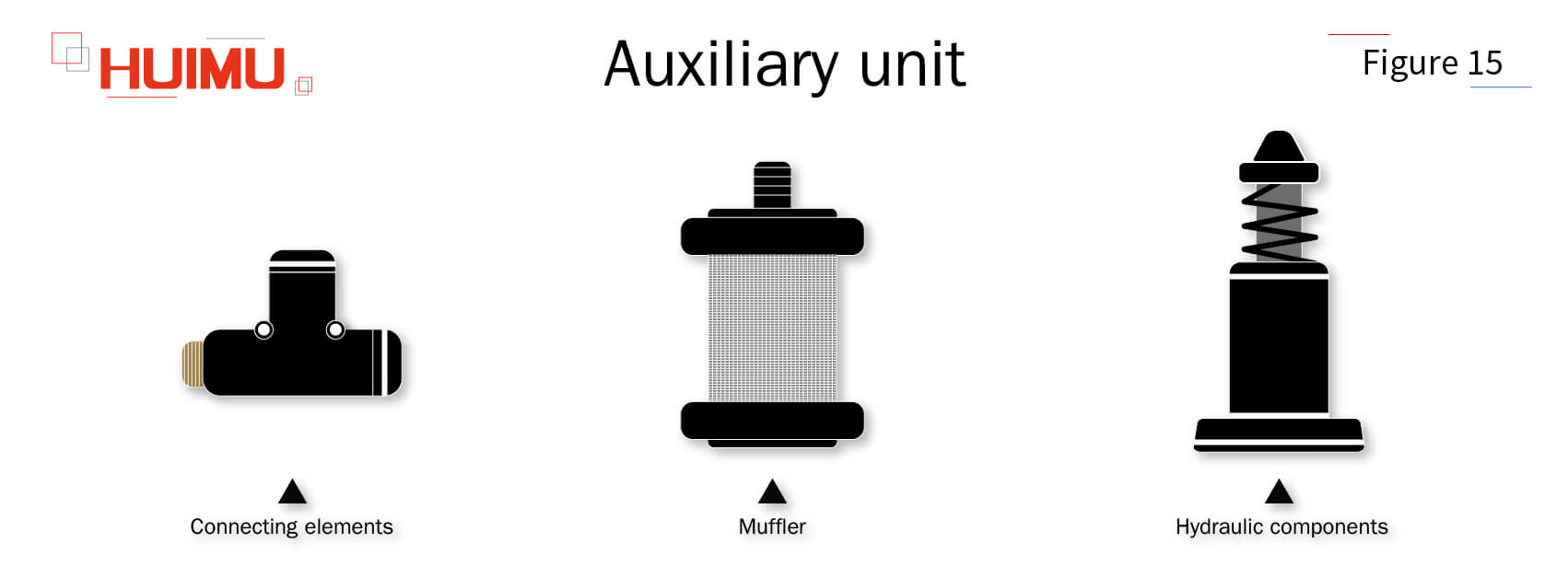
-The auxiliary unit is used to support the operation of the pneumatic system.
5.1 Connecting elements
The connection element is used to connect all pneumatic components together.
5.1.1 Tubing
The tubing, also known as pipeline, is used to connect all devices and fittings of a pneumatic system. Based on pliability, tubing can be divided into rigid tubing and flexible tubing. When designing a pneumatic system, the length and size of the tubing needs to be fully considered. The longer the length of the tubing, the further the compressed air can be transported, but at the same time more compressed air will be wasted, increasing the cost of pressurized air. Larger tubing sizes allow for higher flow rates, less turbulence at the fittings, and lower energy losses, but also increase the overall size and weight of the pneumatic system, as well as manufacturing and maintenance costs. Tubing is usually designed to be sloped so that water vapor remaining in the pneumatic system, after cooling to condensate, will accumulate at the bottom of the tube system and can be discharged through a drain valve.
5.1.2 Fitting
The fitting is used to connect different tubes together. When choosing a tube fitting, it is necessary to consider its thread, size, connection style, etc. At present, most of the pneumatic fittings are quick-disconnect style, which has the advantages of simple structure and easy connection. When connecting fittings, you need to make sure that the ends of the pipes are not beveled and that the fittings are tightly connected, so that air leakage can be effectively avoided.
5.2 Muffler
The muffler is used to eliminate gas noise of pneumatic systems. Some pneumatic components (e.g. cylinders, exhaust valves) will exhaust air when they are working, which cause vibrations and generate gas noise (up to 110dB) due to eddy currents or sudden changes in air pressure. In order to eliminate gas noise and provide a quiet and comfortable working environment, it is usually necessary to install mufflers on the exhaust ports of pneumatic components. There are mainly two types of gas mufflers. The first one is absorption type, that is, to let compressed air rub against porous sound-absorbing materials, and filter out high-frequency noise by converting pressure energy of compressed gas into heat energy; the second one is expansion-interference type, that is, to let compressed air expand in a large aperture chamber, and filter out low-frequency noise by reflection and interference of sound waves.
5.3 Hydraulic components
The advantages of hydraulic components can complement the shortcomings of pneumatic components.
5.3.1 Hydraulic shock absorber
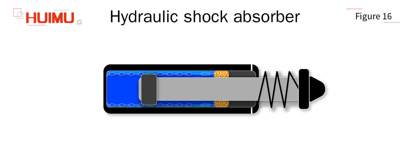
The hydraulic shock absorber, also known as hydraulic cushion, is used to cushion and decelerate objects moving at high speed until they stop, in order to avoid noise, vibration and damage caused by impact energy. The hydraulic shock absorber is mainly composed of shock absorber head, piston rod, piston, bearing, check valve, inner cylinder, outer cylinder, auxiliary spring, energy storage, etc. When an object moving at high speed touches the rubber shock absorber head, the shock absorber head absorbs the first impact of the object together with the auxiliary spring. As the object moves further, the piston compresses the hydraulic oil in the pressure chamber, causing it to flow out of the flow holes in the inner cylinder, and as the piston moves, the number of flow holes gradually decreases and the hydraulic impedance gradually increases, so that the impact energy is converted into heat energy by the dynamic pressure impedance and the object stops moving smoothly. When the object leaves, with the spring reset, the hydraulic oil returns to the pressure chamber through the return hole to prepare for the next cushion.
5.3.2 Pneumatic-hydraulic converter
The pneumatic-hydraulic converter is used to convert pneumatic signals into hydraulic power. Due to the advantages of high power, fast dynamic response and good mechanical rigidity, hydraulic actuators are more suitable than pneumatic actuators for heavy mechanical equipment (e.g. heavy machine tools, trucks, ships, aviation). However, hydraulic systems are poorly adaptable and costly to maintain, so it is an excellent solution to control hydraulic actuators through the pneumatic system. With a pneumatic-hydraulic converter (such as a pneumatic regulator or a pneumatic operating lever), a pneumatic signal can be converted into a hydraulic signal and drive the hydraulic actuator to work.

Get in touch with us now!
Please take a minute or two to complete this simple form to get reply in 24 hours, thank you!
*Please check the trash box of your mailbox, if you do not receive our email.


